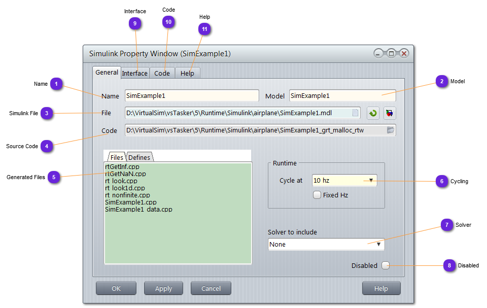
Exclude the Simulink object from the code generation. Disabled Simulink object will not be included into the items using it (entities but not only) without the need to remove it from all users.
Disabling is error prone while removing might leave dangled pointers.
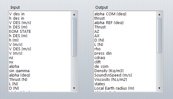
vsTASKER parses the .mdl file and tries to extract all Inputs and Outputs parameters for corresponding structures.
Not all of them shall be used.
The parameters names are listed without underscores. Corresponding unit (if any) is expressed in brackets. For i.e: V DES [m/s] lists the parameter V_DES whose value is in meter per second.
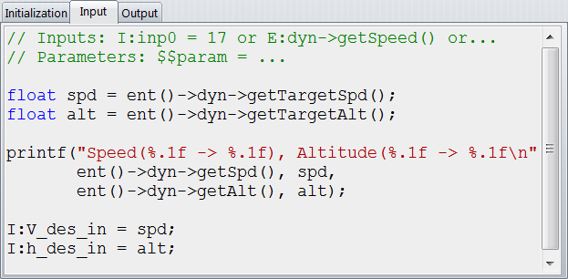
This part is the vsTASKER interface code between the data belonging to the simulation engine and the data pertaining to the Simulink model.
The Initialization part is called at each simulation phase. For i.e, the INIT/RESET phase can be used to initialize the Simulink Input parameters.
The Input part is called before the Simulink model tic() function. Use this code block to extract all the necessary data from the simulation engine objects to set the Input parameters of the Simulink model.
In the following example, we are extracting the requested speed and altitude of our aircraft to set the corresponding Input parameters.
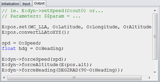
The Output part is called after the Simulink model tic() function. Use this code block to extract all the necessary data from the Output parameters of the Simulink model to set the simulation engine objects.
In the following example, we are extracting the computed speed and heading in our model to update our aircraft.
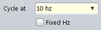
The Input and Output blocks are called at the frequency set in (6).