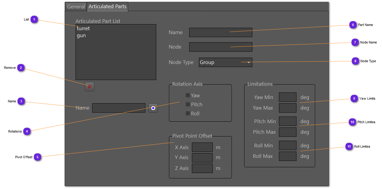
Prepare the articulated parts.
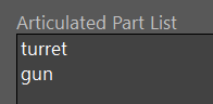
 ListList of all Articulated Parts of the model.
Each name identify the part. The name is logical.
|
|
 RemoveRemove from the list the selected articulated part from the list.
|
|
 NameEnter here the name of the articulated part then use the + to append it in the list.
The name should be unique. Name are logical.
|
|
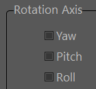
 RotationsCheck here which axis could rotate for the articulation.
|
|
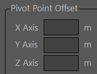
 Pivot OffsetSet the rotation reference pivot from the articulated part origin, in meters.
|
|
 Part NameWhen selected in the list, the articulated part name is displayed in this field.
Can be modified.
|
|
 Node NameName of the node inside the 3D model for the IG to control it. If not known, use a Model Inspector to find it.
|
|
 Node TypeThe articulation part can either be a group or a DOF (degrees of freedom) node (OSG). Select which one the node name refers to.
|
|
 Yaw LimitsSet the minimum and maximum values on the yaw axis (azimuth). For a full unlimited range, use -180, +180.
|
|
 Pitch LimitesSet the minimum and maximum values on the pitch axis (elevation). For a full unlimited range, use -180, +180.
Normal range is -90, +90.
|
|
 Roll LimitesSet the minimum and maximum values on the roll axis (rotation). For a full unlimited range, use -180, +180.
Normal range is -90, +90.
|
|