To properly display this page you need a browser with JavaScript support.
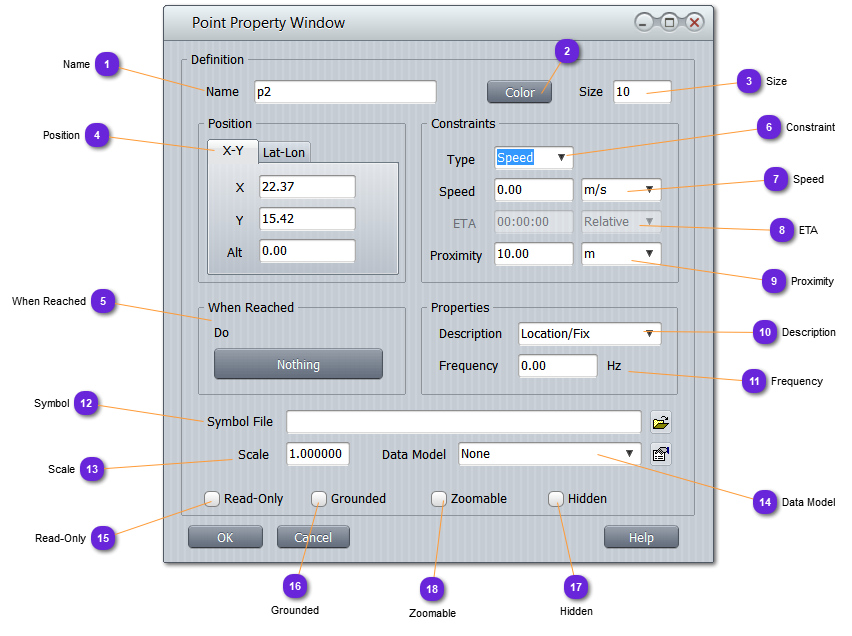
Name Unique name of the point .
Color Color used to draw the default symbol on the map.
Size Size of the default symbol (in pixels).
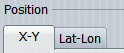
Position Position in coordinates XYZ or latitude, longitude, altitude of the point on the map.
Normally, these values are coming from the mouse positioning at creation time.
Can be updated here manually.
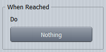
When Reached This event setting is only informative and used by built-in component MotionGoto .
Use can set here any event and trigger it from any user code.
Constraint Specify here the type of constraint that must use the component MotionGoto for any entity having to direct towards the point:
Speed : speed constraint. See (6)
ETA : time constraint. See (7)
Speed If speed constraint is selected, specify here (in the desired unit), the maximum speed the entity must reach to direct towards this point.
MotionGoto uses this constraint but any user component or logic can do the same or adapt this speed.
ETA Estimated Time of Arrival setting. Use this value so that the entity will adapt its speed to reach the point at the desired time:
Relative : duration to observe from the moment the instruction to head towards the point is received.
Absolute : simulation time to observe.
Proximity Minimal distance from the entity to the point used to consider the location reached or not. Used by MotionGoto component.
Description Optional description that can also be used in Radio Navigation scenario.
Frequency Optional frequency value that can be used in Radio Navigation scenario.
Symbol If the default triangle symbol for point must be changed with another textured shape, use this field to specify the file.
Only TGA are supported with alpha channel set for transparencies.
Scale Scale of the textured shape (1 = default size)
Data Model If a data model must be associated with the point (to get extra settings or give specific data to the user code), select it from the drop down list.
To set or change the parameters (interface) of the data model, use the
button.
For example, a point might represent an airport. User can then create a data model named LocAirport with all kind of data some other components or logics might need to process. Using the data model attachment capability, user will be able to specialize any point of his scenario.
Read-Only Check this option so that the user will not be able to move the point.
Grounded Check this option so that the point altitude will always match the terrain level below it (clamped ).
Hidden Check this option to hide the point from the scenario map, when Feature layer not selected.
Hidden features are always visible when the Feature layer is selected.
Zoomable Check this option for the point symbol (or textured shape) will automatically grow or shrink when zoom change.