Logics
Logics are one of the most useful and basic concept of vsTASKER. A logic is a grafcet that connects various objects to represent a flow of sequences.
Each of the objects allowed in a logic have a particular purpose. Combining and linking these objects together can create simple obvious behavior up to complex and unpredictable ones.
|
|
Refer to the Tutorial to learn how to create your own.
|
On the background:
: create a new Logic in the database. Can also use

from the toolbar.
: list all exported Logics available in /Data/Shared directory
: select all Logics of the database (useful for moving symbols or deleting them).
When a Logic is selected:
: give the current Logic to the Entity listed in the sub list. Faster than to go through the Behavior panel.
: open the Logic property window.
: See the content. Same as double clicking.
: Give a new name to the Logic.
: Copy the Logic into the clipboard.
: Force all dangled arrows to attach to the closest anchor. This is useful after some copy/paste or undelete.
To add objects into a logic, you must first select which object to add using the vertical Toolbar shown here. Then, clicking anywhere on the Drawing Area (Diagram) creates the designated object displaying its own symbol.
 Entry Point (EPoint, green head) and Exit Point (XPoint, red head) cannot be added alone. They must be attached to another object. If another object is already selected, clicking the EPoint or XPoint button will immediately create and attach the point to it. Otherwise, cursor will change until an object is designated into the diagram for dropping the point.
For EPoint or XPoint property windows, see here.

Add a
Text for comment.
|
|
Logic objects does not inherit from the logic. They are embed into the logic (or another group).
|
All objects have one or two connectors (orange head below them).
The connector can have several modes:
-
Done: orange head, default. Object processing is finished.
-
Quit: red head. Object processing is finished and the level (Group, Context, Knowledge or Logic) must be quit.
-
Connect: arrow head. When object processing is finished, another object must be instanciated.
-
Immediate: allowed for Action only, force the next object to be processed inside the same cycle and not the following one.
-
Nothing: connector is not visible. Nothing is like Done but without graphical representation.
 To connect one object to one another, click the connector head with the mouse while maintaining down the left button then drag it toward the other object.
 When close enough, the target object shows magenta anchors. Release the mouse while close to one of these anchors.
To disconnect one object, select the arrow head and move it away from any anchor, then release.
The arrow changes to orange head (Done mode, default).
|
|
A connector cannot be connected to its parent, except for Task and Group objects. Use the entry point to do so.
|
In order to create a group that will gather sub-logics, do the following:
Select one or more objects of a current logic.
Right click and select the option.
A group is then created. It contains all selected objects.
A group can be seen as a logic part. It has an entry point and an exit point.
A group can also embed other groups.
Several groups can run concurrently inside the same logic (or group).
Like a logic, a group has a specific property window. See
here.
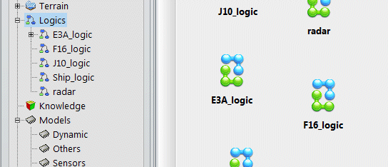
During runtime, when an entity is selected, the behavior panel shows all logics currently running (magenta).
Double click any of these symbol (J10_logic for the example above) to open the definition.
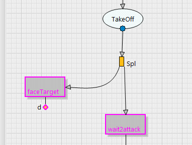
The magenta outlines highlight in real time running objects or transiting connections. The runtime monitoring sequence visually the logical flow.