vsTASKER 7 User Manual
×
Menu
Index

Socket Property

 
A Socket object in vsTASKER is a convenient way to send or receive data using the network card and TCP/UDP protocol.
The setting of such object remains simple and the user just has to concentrate on what to send and what to do with the received data.
One SockItem cannot send and received at the same time. It is either a sender or a receiver. Different ports shall be used for now.
 
 
Socket Property
1

Name

1. Name
Name the SockItem. Must be unique.
 
2

Type

2. Type
Select from the drop down list whether the protocol will be UDP or TCP.
UDP is a faster protocol but which is not reliable. Also, UDP can broadcast more easily than with TCP.
 
3

Mode

3. Mode
Each SockItem can either send or receive. If the mode is changed, the position of the icon on the diagram will also change.
 
4

Port

4. Port
Specify the port to use. Note that there should be one port per SockItem.
 
5

IP Address

5. IP Address
IP address which will be used to listen on a particular port.
Use button to retrieve the current computer IP.
 
6

Config

6. Config
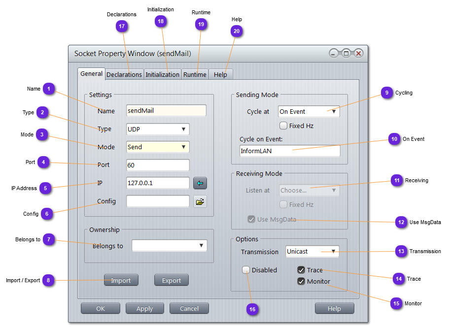
If the setting must be done from a configuration file, so that to be adaptable from another code, without having to open vsTASKER and change the setting, specify here the configuration file that will be used by the SockItem at creating time, on the simulation engine, for setup. The file must exist and be accessible at runtime.
Content of the file shall be the following, in a text file:
# IP, port, cast (unicast | broadcast | multicast)
127.0.0.1, 50, unicast
 
7

Belongs to

7. Belongs to
If the SockItem must use a particular entity data, select it here if it already exist in the scenario.
The variable entity will be set at runtime.
Otherwise, the following code in the Initialization panel (RESET phase) will do the trick:
     entity = S:findEntity("myEntity");
 
8

Import / Export

8. Import / Export
Use Import to replace the current SockItem with a previously exported one.
Use Export to save the current SockItem to a file for later retrieval or sharing.
Default location is /Data/Shared. Extension is skt.
 
9

Cycling

9. Cycling
Chose the frequency at which the runtime code of the SockItem will be called. If On_Event, call happens only when the proper event is received (10).
If Fixed Hz is checked, the frequency will the the wall clock one and not the simulation clock.
(only for Emitters).
 
10

On Event

10. On Event
Put here all events that will trigger the runtime code for one cycle. Must be separated with comas if many.
(Only for Emitters)
 
11

Receiving

11. Receiving
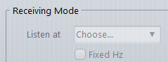
Specify here at which frequency the SockItem runtime code will be called to process the received data.
If the frequency of the receiver is lower than the one of the sender, some data will be lost as they are not pooled (on UDP). If the frequency of the receiver is higher then the one of the sender, some calls will just be skipped because of no new data available.
(Only for Receivers)
 
12

Use MsgData

12. Use MsgData
For receivers, MsgData can be expected as a header of the message. This is convenient for casting the message into the correct class object.
Sometime, when the sender does not inherit from MsgData, uncheck this option.
The runtime code will get raw data and it must handle itself the marshmalling of the data from the socket buffer.
 
13

Transmission

13. Transmission
Select from the drop down list the kind of transmission the socket will operate. Bear in mind that some casting require special IP addresses.
Unicast: default, peer to peer communication. Local 127.0.0.1 or any other IP will do.
Multicast: unique emitter and multiple receiver. Multicast addresses range from 224.0.0.0 to 239.255.255.255. Receivers must register to the multicast group address. (UDP only)
Broadcast: all nodes of the subnet will see the traffic (UDP only).
 
14

Trace

14. Trace
When checked, the console will output all connection success failure, data entry or sending, and SockItem states.
 
15

Monitor

15. Monitor
When checked, the SockItem icon will change color according to the inner state sent by the simulation engine:
  • Greyed out: disabled
  • Green: socket created, no data
  • Magenta: data passing through
  • Red: connection failed.
 
16

Disabled

16.
If checked, the SockItem will not be created and there will be no communication performed (nor the socket created).
 
17

Declarations

17. Declarations
Put in this panel all data you want to add in the current SockItem. Public data is used to generate the Dyn-UI so, consider carefully what you put in the Public: data section.
No constructor and destructor should be added here. Use instead the Initialization panel.
18

Initialization

18. Initialization
This part is called automatically at instantiation (INIT), when SockItem is created using new, or every time the object is RESET and finally at destruction (CLEAN) using delete.
It is a good practice to put in the RESET part whatever must be reinitialized at reset. There is no break after INIT to allow the RESET part to be processed after INIT, at Socket creation time.
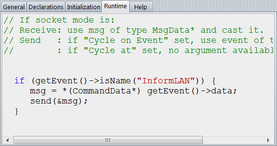
19

Runtime

19. Runtime
This part is called by tic(Event*) at the specified frequency. It is an automatic routine of the SockItem so, all data of the SockItem can be accessed here.
 
  • Senders: if triggering mode is Cycle on Event, use event of type Event*. if Cycle at set, no argument is available. Use scen() to get the data you need.
     
  • Receivers: Use msg of type MsgData* and cast it according to the type of data you are expected on this socket.
    Sometimes, the number of messages are numerous and to not wait for the next cycle to read the queued ones, use return AGAIN; but beware of blocking the simulation if continuous messages are coming. Better put a limit in the number or return AGAIN allowed per cycle.
 
 
20

Help

20. Help
Any description of the SockItem can be put here and will be used for the automatic document generation (see Make Documents)