vsTASKER 7 User Manual
×
Menu
Index

General

 
General
1

Name

1. Name
Entity name that must be unique. Cannot hold spaces or some special characters.
Unicode characters can be used here (Asian characters for example).
 
2

Class

2. Class
By default, an entity inherit from the Entity class. Select here another class for the entity using ...
Use to open the class code window.
 
3

Profile

3. Profile
 
4

Catalog

4. Catalog
If the class has been instanciated from a Catalog entity, the originating name will be displayed here. Cannot be changed unless Reference is selected.
 
5

Reference

5. Reference
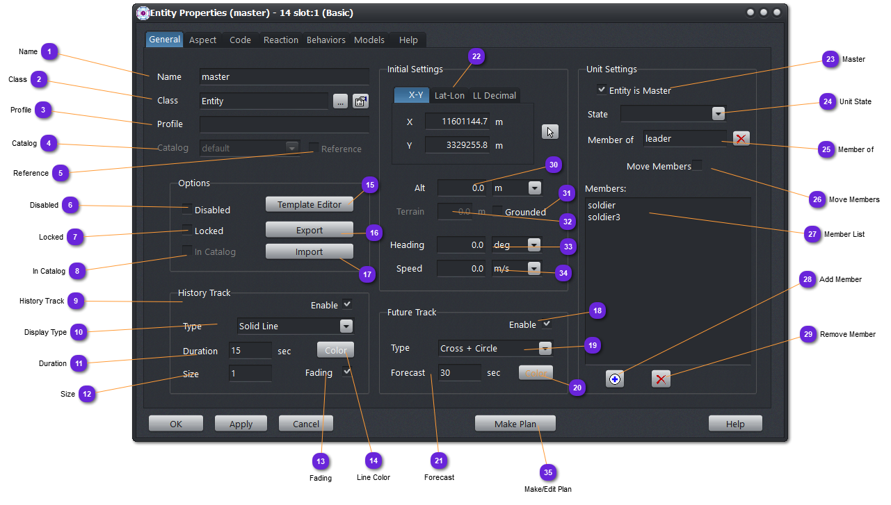
If Reference is checked, the entity will not be modifiable individually. Only the Catalog entity can be. At runtime, all the "reference" entities will be instanciated based on the specified catalog (same as for runtime entities). Only name and position of the entity can then be set at design time.
"Reference" entities are handful when they are numerous and depend on behavior definition that can change for all of them, instead of propagating the change individually which can be tedious and error prone.
When checked, as the entity is only a link, the Catalog name can be changed at anytime during design.
Not available yet.
6

Disabled

6. Disabled
Check this to disable the entity without removing it from the scenario.
Disabled entities no more exist for the simulation even if they have a memory footprint and a data persistency in the runtime engine.
When an entity is disabled, it is created and is ready to be activated but will not exist from the scenario perspective.
 
7

Locked

7. Locked
Check this to prevent the entity to be accidentally deleted or moved. Code and behavior cannot also be modified.
 
8

In Catalog

8. In Catalog
Not used for now.
 
9

History Track

9. History Track
When Enabled, the previous entity positions recorded by the GUI will be recorded and displayed on the map according to Type.
History Track can be controlled from the code using the Entity API (entities.h)
 
10

Line Type

10. Display Type
Chose here the style of the history line, from stream of dots to, dash or simply a solid line.
 
11

Line Duration

11. Duration
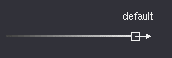
Specify here in seconds how long in the past will be the recording.
If the duration is 15 seconds, that means that the beginning of the history line displayed marks the entity position 15 seconds before the current time.
 
12

Size

12. Size
Size of the history line or width of the dot. Default is 1 for the line and 2 for the dot.
 
13

Fading

13. Fading
When enabled, the history line will fade from full brightness at start to black at tail. Default setting.
 
14

Line Color

14. Line Color
Line color of the history (track) line. By default or when the selected color is pure black (0x00) the entity color is used.
 
15

Template Editor

15.
See explanations here.
 
16

Export

16.
Will export the current scenario to an ASCII file for exchange (or re-use). Not all data is exported. Scenario does not export entities, only catalogs.
 
17

Import

17.
Will import (by overwriting the current scenario) a previously saved scenario. Name will also be changed. All current scenario data will be lost.
 
18

Future Track

18.
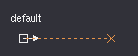
When activated, will display a visual cue in front of the entity, forecasting the position the entity will reach in a specified number of seconds, according to the actual speed and heading.
Future track can be controlled from the code using Entity API (entities.h)
 
 
The Future Track is not displayed when speed is around zero
 
19

Display Type

19.
Select the visual cue displayed for the forecasted position:
  • X Cross
  • Circle (empty)
  • Circle with a X cross
A dashed line will connect the cue and the entity.
 
20

Future Track Color

20.
Set the color of the visual cue and dashed line for the Future Track.
Default is light orange which is good in both themes (dark and light).
Can be changed during runtime.
 
21

Forecast

21. Forecast
Set here the number of seconds to use to compute the position ahead. If zero, the Future Track is not displayed.
Default is 30 seconds.
 
22

Position

22.
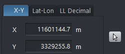
Position of the entity on the terrain coordinates. X-Y, Lat-Lon or Decimal Lat-Lon can be used for clarity. Use Apply when modifying the values in the text field.
If button is used, the property window will vanish until user click on the terrain map to select the position. Property window will appear again with the new coordinates updated.
 
23

Master

23. Master
If checked, the entity will become Master of the unit (composed by itself plus the members).
See here for more details on how to work with Units/Aggregates.
 
24

Unit State

24. Unit State
A unit can aggregate all its members, making them invisible and not selectable (but all of them will still be simulated).
If disaggregated, all entities will be visible and selectable but will be part of a unit and will be linked to the Master entity.
 
 
25

Member of

25. Member of
If the entity is a member of a Unit (and a member can also be a Unit itself for hierarchical aggregates), the name of the Master is notified here.
Selecting removed the current entity from the Master unit.
 
26

Move Members

26. Move Members
When checked, disaggregated members will be displaced with the master, at design and runtime, when relocation is performed using the mouse or coordinates reposition.
This can be handful when a platoon or a battalion must be displaced from one terrain location to one another, without reorganization.
If not checked, the master entity will be relocated alone.
 
27

Member List

27. Member List
List of all entity members of this unit.
 
28

Add Member

28. Add Member
Used to add another entity as a member of this unit. The list of available entities are not members of unit.
 
29

Remove Member

29. Remove Member
Select one or many entities from the above list and use this button to remove them from the unit.
Entities are not deleted, just moved out of this unit.
 
30

Altitude

30.
Initial altitude of the entity in the select unit. Changing the unit will also change the displayed value. Altitude is always above sea level. Shall be negative for submarines.
 
31

Grounded

31.
If checked, the altitude (Z factor) of the entity will match the terrain altitude (clamping). This is handful for land entities.
This is only for design time. A grounded entity will not necessarily be grounded by the dynamic model (if the model does not check this flag).
Checking Grounded insure that if the (land) entity will always be at the correct altitude even if moved during the scenario design.
 
32

Terrain Altitude

32.
Display the terrain altitude (if any terrain layer provided into the scenario) below the entity position.
 
33

Heading

33.
Initial heading of the entity expressed in the selected unit. Changing the unit will also change the displayed value.
Values are [-180,180] degrees.
 
34

Speed

34.
Initial speed of the entity expressed in the selected unit. Changing the unit will also change the displayed value.
The value is not bound by the dynamic model minimum and maximum values at design.
 
35

Make/Edit Plan

35. Make/Edit Plan
Use this button to create or update a Plan for this entity.
See here for how to work with plans.