vsTASKER 7 User Manual
×
Menu
Index

Aspect

 
Aspect
1

2D GUI/SIM

1.
This block defines the aspect of the entity in the vsTASKER GUI terrain map.
 
2

Visibility

2. Visibility
Check this to make the entity symbol visible on the map (otherwise, will not be visible).
 
3

Heading

3. Heading
If checked, the heading will be represented as a little arrow aligned with the entity heading. Up meaning north.
 
4

Hdg/Spd

4. Hdg/Spd
If checked, the length of the heading arrow will be proportional to the speed (the higher the speed, the longest the line).
 
5

Labeling

5. Labeling
Set the font for the entity labeling and the display mode for both GUI and SIM map.
See here for a complete description.
 
6

Symbol Type

6. Symbol Type
Select here the kind of symbol for the entity display:
  • None: No symbol
  • Normal: Default little empty square
  • Normal Filled: Default little filled square
  • Dot: OpenGL dot (square or round according to OpenGL smoothing mode)
  • Bitmap File: Select it in (8)
  • Symbol: Predefined symbols loaded in Preferences. See here.
  • 2525B: List of Military standard symbols.
  • Vessel: little oriented filled triangle.
 
7

Symbol List

7. Symbol List
Select the kind of predefined symbols extracted from the list. See here for more details about the lists.
 
8

Filename

8. Filename
If Bitmap File is selected, enter here (or browse) for the bitmap file to load and apply as a texture.
 
9

Scale

9. Scale
Scale alteration of the loaded bitmap. Scale value will be applied equally on the width and height of the symbol.
If Dynamic is checked, the size of the bitmap will vary according to the zoom level. The higher the zoom, the bigger the symbol. If Dynamic is unchecked, size of the bitmap is unchanged whatever the zoom level.
 
10

Rotate

10. Rotate
If checked, the symbol (bitmap only) will rotate with the heading. This has no effect on Normal, Normal Filled and Dot symbols.
 
11

Preview

11.
If possible, the selected symbol type will be displayed on the preview square.
 
12

Color

12.
Color of the drawn symbol for types Normal, Normal Filled and Dot.
The color must not be confused with the force (IFF) of the entity.
13

3D GUI

13.
This block is for the Perspective and Globe views that uses the OpenGL library for display.
The specified 3D models must be loadable under OpenGL.
 
14

Copier

14.
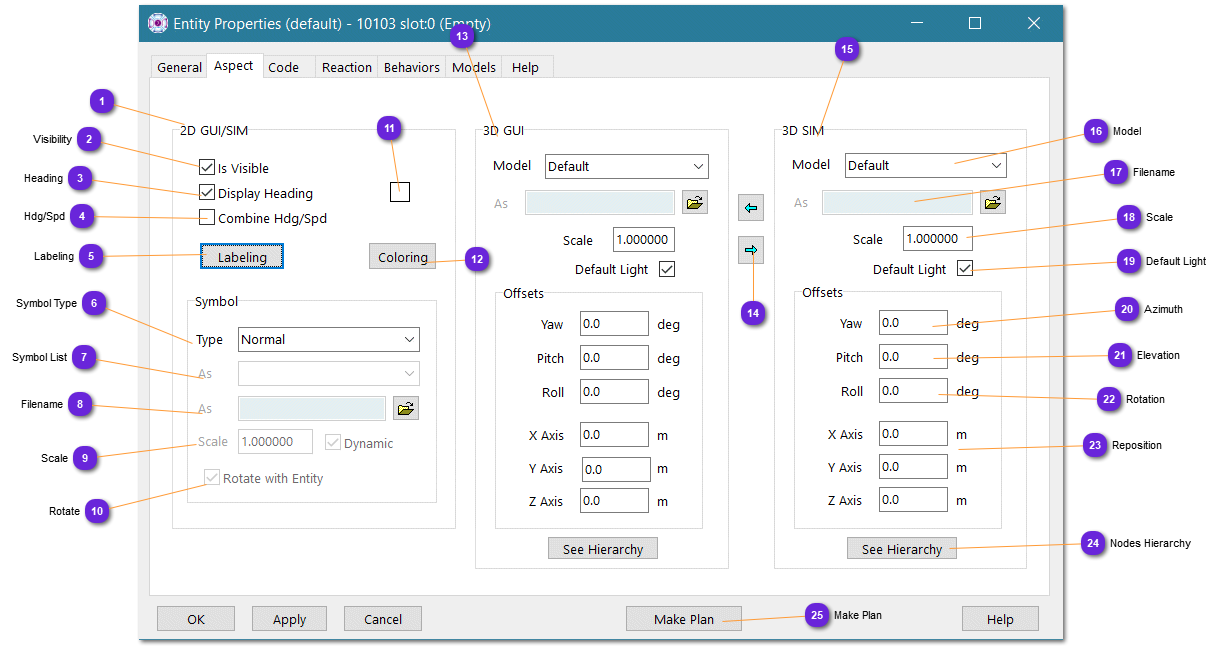
Use these buttons to copy all values from 3D GUI block to 3D SIM block or reverse. This can be useful when the Editor 3D is used as a tester for model and offset settings before forcing the simulation engine (stealth) to use the same.
 
15

3D SIM

15.
This block is for the simulation engine output and will be used by the 3D library specified by the selected Viewer.
vsTASKER GUI will try to load these models into OSG when 3D Editor mode is selected.
If the model cannot be loaded by OSG plugins, it will not be displayed on the 3D Editor but might/will into the simulation engine if the correct 3D engine library supports it.
 
16

Model

16. Model
Type of the model (file) to load. Even if not mandatory, it is a good practice to make both the file and the setting correlated as the code generation might use the Model setting to call the proper loader, regardless of the file model type.
  • None: No model to load
  • 3DS Max: Autodesk 3ds format
  • OpenFlight: Multigen/Presagis flt format
  • OpenSceneGraph: osg or ive format
  • Bitmap: Any raster file
  • Delta3D: OSG format
  • Collada: XML dae format
 
17

Filename

17. Filename
Enter here (or browse) the 3D model file (according to the chosen type above).
The full path will be stored. It is not possible yet to specify a relative path for 3D model files.
 
18

Scale

18. Scale
Enter here the scale factor that will be applied to the loaded 3D model by the graphic engine (1 means unchanged, 0.5 is two times smaller, 3 is three times bigger)
 
19

Default Light

19. Default Light
When checked, the model will be illuminated with the default light (if any defined). When unchecked, ambient lightning is used.
This setting is for OpenSceneGraph only. Sometimes, some objects appear totally white in some lightning conditions. Changing this mode restore the texture.
 
20

Azimuth

20. Azimuth
If the 3D model needs to be turned around the Z axis (heading effect), enter here the values in degrees. 0 means no offset.
 
21

Elevation

21. Elevation
If the 3D model needs to be turned around the X axis (pitch effect), enter here the values in degrees. 0 means no offset.
 
22

Rotation

22. Rotation
If the 3D model needs to be turned around the Y axis (roll effect), enter here the values in degrees. 0 means no offset.
 
23

Reposition

23. Reposition
If the center of gravity of the 3D model must be displaced, enter here the offset value in meters.
In some models, the center of gravity is the lowest part of the model, in some, it is the middle part.
The Z value helps clamping visually a ground entity.
 
24

Nodes Hierarchy

24. Nodes Hierarchy
This button will call an OpenSceneGraph command which will load the model and print out on a console window the hierarchy of nodes.
This can be useful in case articulated parts have to be found for manipulation with a specific component.
Result depends on the model definition itself. Some has named nodes, some not.
 
25

Make Plan

25. Make Plan
Call the Plan definition window. See here for complete description.