vsTASKER 7 User Manual
×
Menu
Index

Settings

 
Settings
1

Type

1. Type
Chose in the list which type of path to use for the pattern. See here.
  • Creeping U
  • Creeping L
  • Holding
  • 8 Shape
  • Circular
  • Spiral
  • Sectors
  • User Defined
 
2

Loop

2. Loop
Set the one time only of do it again mode.
If No is selected, pattern will be left when exit point is reached.
If Yes is selected, pattern will be followed again according to Mode (3) when extremity point is reached.
 
3

Mode

3. Mode
Use to define the loop mode (2) when activated.
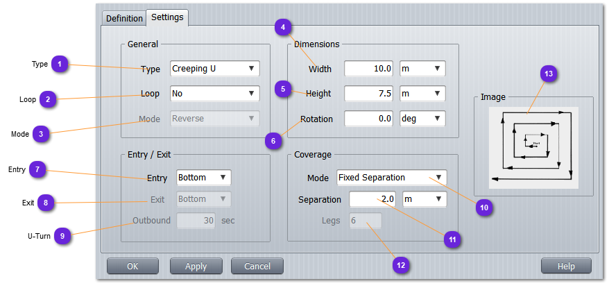
  • Reverse: component manager will initiate a special maneuver to recede from the extremity point, then U-turn before entering the pattern from the last extremity point.
  • Continue: works only with some circular kind of shapes. Exit point will be headed only when the component manager will receive the order to leave.
  • Restart: component will guide the entity towards the entry point again using a predefined procedure which removes the aircraft from the reentry point until it is able to properly return without over shooting too much during the U-turn.
 
4

Width

4.
Width of the rectangular area, in the selected unit. User modifiable.
 
5

Height

5.
Height of the rectangular area, in the selected unit. User modifiable.
 
6

Rotation

6.
Rotation angle of the rectangular area, in the selected unit. 0 for horizontal, 90 for vertical (in degrees). User modifiable.
 
7

Entry

7. Entry
Position of the entry point regarding the rectangular area.
  • Top: upper part of the area.
  • Bottom: lower part of the area.
 
8

Exit

8. Exit
Position of the exit point regarding the rectangular area.
  • Top: upper part of the area.
  • Bottom: lower part of the area.
 
9

U-Turn

9. U-Turn
In case of Reverse mode (3), specify the time in seconds the entity will recede before engaging the U-turn maneuver.
 
10

Creeping

10.
Works only for type Creeping U and Creeping L
Specify how the legs must be computed to fill the rectangular area
  • Fixed Separation: legs will be spaced with the same exact value specified in Separation (11). It might not fill the area for big values of the ratio width / separation.
  • Fixed Number of Legs: legs will be spaced with a computed value width / legs.
 
11

Separation

11.
Set here the intended separation value between legs of the creeping shape.
 
12

Legs

12.
Set here the intended number of legs to be used for the creeping shape.
 
13

Preview

13.
Not available